1A: Onshape Fundamentals - Section 1
Exercise 4: Sketching the Drivetrain Frame
Now that you’ve sketched individual parts, it's time to create a full drivetrain frame.
In the document you copied previously, navigate to the part studio for Exercise 4.
Watch the video below and follow along to create your drivetrain sketch while learning and practicing several part creation techniques.
Warning
2823 -- This is the first time you will see the "Orgin Cube" featurescript, though it is not mentioned. We will not use the orgin cube in the future and anywhere it mentions it in these lessons you can just use a mate connection to the Orgin.
Warning
2823 -- This lesson has you make a plane referencing a mate connector. For the purpose of the lesson follow along, but when making reference planes use geometry such as part faces, or points on a sketch instead of mate connectors.
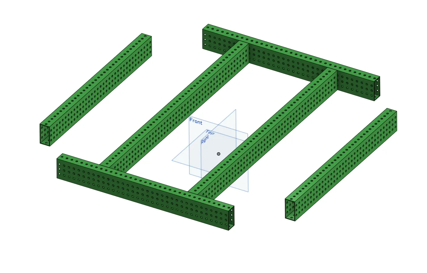
Your goal is to sketch and extrude the rectangles shown below, then convert them into tubes them using Tube Converter.
Tip
Make sure to mirror or pattern your sketches using construction lines — don't manually draw both sides.
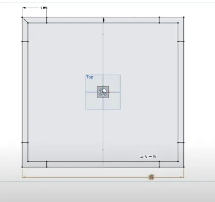
Important Notes for the Sketches
- Make sure to mirror across both X and Y axes.
- Avoid overdimensioning your sketches — use symmetry whenever possible.
- Make sure the cross beams are also mirrored properly.
- Use the origin as the center reference point for everything.
If your sketch is fully constrained (everything turns black), you’re doing it right! You can now use extrude and tube converter to turn the sketch into your drivetrain box tubes.
Finishing Up
- Add cross rails as you did in the last exercise to complete the drivetrain tubes.
- Double-check that no parts are fused together incorrectly.
- Use the dot and top plane (origin and ground) to verify alignment.
- Make sure tubes line up properly with the module placements.
Once you're done with the above tasks and checks, move on to the next exercise.